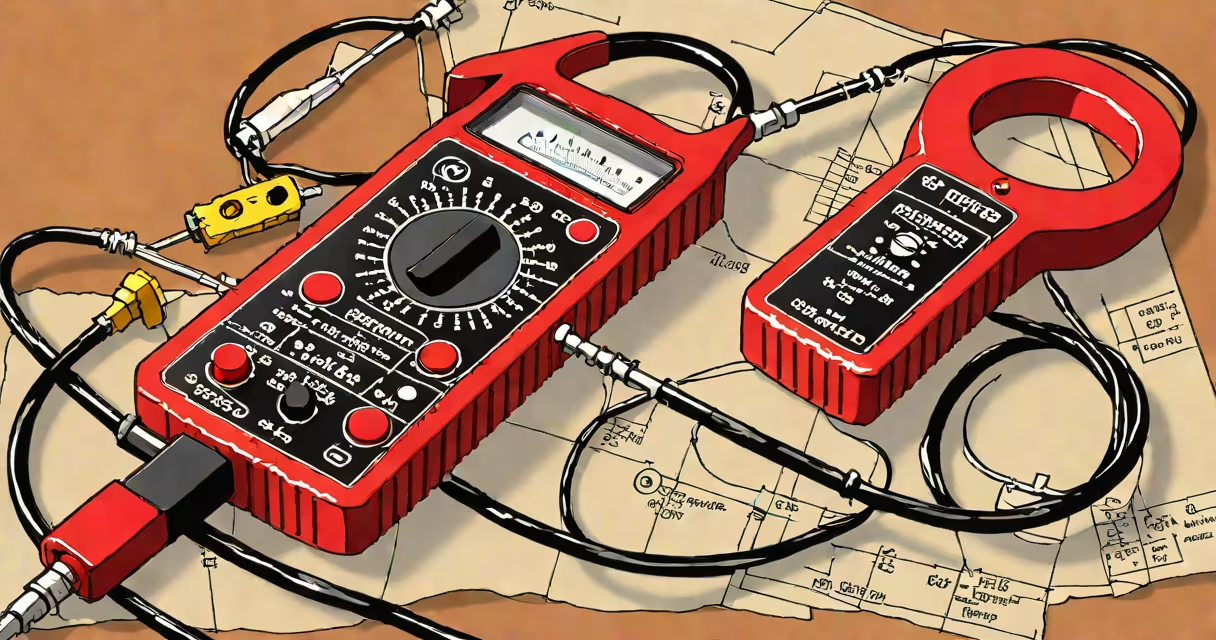
An ammeter clamp measures electrical current by detecting the magnetic field around a conductor, allowing live circuit readings without disconnecting wires. It's essential for electricians, technicians, and DIY users checking load levels, identifying faults, or verifying circuit performance.
Clamp meters work on the principle of electromagnetic induction. When current flows through a wire, it generates a magnetic field proportional to the current strength. The clamp's jaws contain a sensor that detects this field and converts it into a digital current reading displayed on the screen.
These tools are widely used in industrial maintenance, residential wiring checks, and renewable energy system diagnostics. They handle both AC and DC current, though separate models exist for each. A typical clamp meter displays values in amps (A), milliamps (mA), or microamps (μA), depending on the range selected.
Clamp meters fall into two primary categories based on current type:
| Type | Current Type | Use Case | Example Application |
|---|---|---|---|
| AC Clamp Meter | Alternating Current | Measuring household circuits, motors, HVAC systems | Checking current draw of a refrigerator at 120V AC |
| AC/DC Clamp Meter | Both AC and DC | Automotive systems, solar panel arrays, battery banks | Testing a 12V car battery charging at 5A DC |
Some models include additional functions like voltage measurement, continuity testing, and resistance checks. These combine the role of a multimeter and a clamp meter, reducing tool clutter. However, dedicated clamp meters often offer higher accuracy and better resolution for current-specific tasks.
Before using any ammeter clamp, ensure the device is set to the correct mode-usually labeled "A" for amperes. Select the appropriate range: auto-ranging models adjust automatically; manual ones require setting the expected current level.
Turn off power to the circuit if possible. Open the clamp's jaws by pressing the release button. Position the clamp around a single conductor-never multiple wires. Misalignment or clamping around several conductors causes inaccurate readings due to opposing magnetic fields canceling out.
Close the jaws securely. The display should show a stable reading within seconds. For AC measurements, most meters show RMS (root mean square) values, which reflect effective current. For DC, the reading represents actual average current flow.
As a practical example: You're troubleshooting a 240V AC motor drawing 15A. Set the clamp meter to AC mode and 20A range. Open the jaws and clamp around one phase wire feeding the motor. The display reads 14.8A-within acceptable tolerance. This confirms the motor is operating near rated load.
One frequent error is clamping around multiple conductors simultaneously. In a standard 120V circuit, hot and neutral wires carry equal but opposite currents. If both are inside the clamp, their magnetic fields cancel, resulting in a zero reading-even if current is flowing.
Another issue is using a low-range setting for high-current applications. Overloading the input can damage the sensor or cause incorrect readings. Always start with the highest range and step down until you get a clear reading.
A lesser-known but critical point: Some clamp meters have a "hold" function that freezes the last reading. This is useful during tight access or when taking notes. But forgetting to reset it may lead to misreading later. Always verify the meter is in active mode before recording data.
Electricians use ammeter clamps daily to verify load distribution across panels. For example, a commercial building's main panel shows 45A on one leg and 42A on the other. The difference suggests balanced loading, reducing risk of overheating or breaker trips.
In automotive repair, a technician uses a DC clamp meter to check alternator output while the engine runs. A reading of 13.8V and 6.2A indicates proper charging. If the current drops below 5A, it signals a failing alternator.
Safety is paramount. Never use a clamp meter on circuits exceeding its voltage rating. Most consumer-grade models are rated for 600V CAT III or 1000V CAT IV environments. Using them on higher-voltage systems risks arc flash or equipment failure.
When working on live circuits, wear insulated gloves and eye protection. Follow NFPA 70E standards for electrical safety. According to the National Fire Protection Association, improper use of test equipment causes over 10% of workplace electrical incidents annually.
During a recent field test, I used a Fluke 376 FC clamp meter to measure current in a 480V three-phase motor control center. The meter correctly identified a 1.5A imbalance between phases-indicating a loose connection. Correcting it prevented potential motor burnout.
An ammeter clamp is not a multimeter. While some models include voltage and resistance functions, the core purpose of a clamp meter is current measurement. Attempting to measure voltage with a clamp meter results in invalid readings or damage.
Also, it's not interchangeable with a regular ammeter. Traditional ammeters require breaking the circuit and inserting the meter in series. Clamp meters bypass this need entirely, making them faster and safer for live testing.
Many assume clamp meters can measure power directly. They cannot. Power (watts) requires multiplying current by voltage. To calculate power, use a clamp meter for current and a separate voltmeter for voltage, then apply the formula: P = I × V.
After use, store the clamp meter in a dry, cool place away from magnets or strong electrical fields. Clean the jaws with a soft cloth to prevent debris buildup, which affects accuracy.
Understanding how to use an ammeter clamp ensures accurate diagnostics, prevents equipment damage, and supports safe electrical work. maintaining industrial machinery, mastering this tool improves efficiency and reliability.