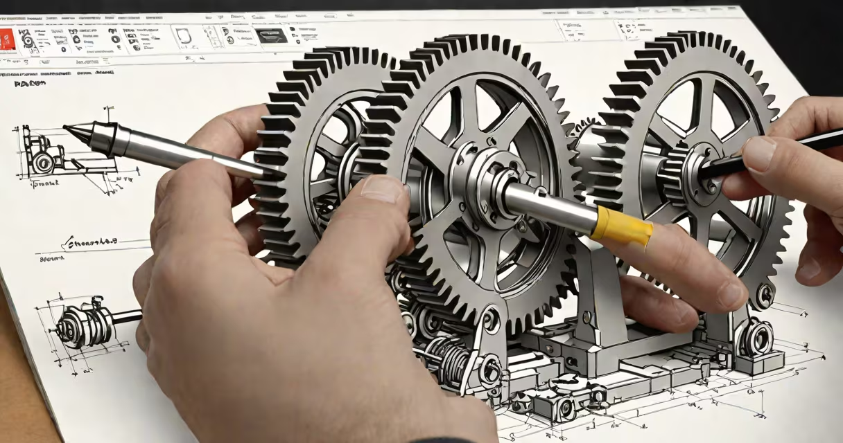
Drafting in engineering is the process of creating detailed technical drawings that communicate the dimensions, materials, tolerances, and assembly instructions for physical components or structures. These drawings serve as the primary communication tool between engineers, manufacturers, and builders.
Engineers use drafting to translate abstract ideas into precise, measurable representations. A single part drawing may include multiple views-front, side, top-and annotations specifying material grade, surface finish, and allowable variation. Without accurate drafting, manufactured parts won't fit together, systems fail, and projects exceed budgets.
Modern drafting relies heavily on computer-aided design (CAD) software such as AutoCAD, SolidWorks, and CATIA. These tools allow engineers to model parts in three dimensions, simulate movement, and generate 2D orthographic projections automatically. The output is not just a sketch-it's a production-ready document that defines every aspect of a component's geometry.
Drafting begins with a concept or requirement. An engineer receives a design brief-say, to build a custom gearbox for a robotic arm. They start by sketching rough layouts, then move to CAD software to define exact shapes, sizes, and relationships between parts.
Each drawing follows standardized conventions. For example, hidden lines are dashed, centerlines are alternating long and short strokes, and dimension lines connect measurements to specific features. These rules ensure consistency across teams and industries. The American Society of Mechanical Engineers (ASME) publishes the Y14.5 standard, which governs geometric dimensioning and tolerancing (GD&T)-a critical layer of precision in industrial drafting.
Once finalized, the draft is reviewed by peers and often approved through a formal sign-off process. Only after approval does it move to manufacturing. A missing tolerance or incorrect scale can result in a part that doesn't assemble or fails under load. One misaligned bolt hole in a spacecraft mounting bracket led to a $125 million mission failure during the 1999 Mars Climate Orbiter incident-a known case where poor documentation contributed to hardware loss.
Engineering drafting varies by field. The most common types are mechanical, civil, electrical, and architectural drafting. Each uses specialized symbols, scales, and standards.
| Type | Primary Use | Common Tools | Standard Reference |
|---|---|---|---|
| Mechanical | Parts, assemblies, machine components | SolidWorks, AutoCAD, Creo | ASME Y14.5 |
| Civil | Highways, bridges, drainage systems | AutoCAD Civil 3D, MicroStation | AISC, ACI codes |
| Electrical | Circuit layouts, wiring diagrams | Electrical CAD, Altium Designer | NEC (National Electrical Code) |
| Architectural | Buildings, floor plans, structural details | Revit, SketchUp, AutoCAD Architecture | IBC, ADA standards |
For example, a civil engineer designing a stormwater drain system creates cross-sections showing pipe diameter, slope, and flow rate. These drawings must account for soil type, rainfall intensity, and local regulations. A miscalculation in slope can cause flooding or pipe erosion. The U.S. Army Corps of Engineers requires all flood control project designs to follow strict drafting protocols to prevent failures during extreme weather events.
Drafting is not the same as sketching or modeling. A hand-drawn sketch may convey intent but lacks the precision needed for fabrication. Modeling in 3D software like Fusion 360 shows form and motion but doesn't replace the annotated 2D drawing required for CNC machining or quality inspection.
Another misconception is that drafting is obsolete due to advanced simulation tools. This is false. Even with finite element analysis (FEA) and computational fluid dynamics (CFD), engineers still rely on drafting to define the actual geometry that gets manufactured. Simulation results depend entirely on the input model-and that model must be accurately drafted.
A key distinction lies in the difference between drafting and design. Design involves problem-solving, creativity, and trade-off analysis. Drafting is about accuracy, clarity, and compliance. An engineer might spend weeks iterating on a design concept-changing materials, adjusting load paths, testing alternatives-but only once the design is finalized does drafting begin. The act of drafting locks in the final form.
Consider a team designing a gear housing for a wind turbine gearbox. The housing must withstand high torque, resist corrosion, and allow access for maintenance. The lead mechanical engineer starts by defining the outer shell shape using a CAD program. They specify a cast aluminum alloy (A356-T6), wall thickness of 12 mm, and internal ribs for stiffness.
Next, they add dimensions: 300 mm diameter, 150 mm height, with four M12 threaded holes spaced evenly around the base. They apply GD&T to ensure the bore for the shaft is within ±0.05 mm of true position. The drawing includes a section view showing internal ribbing and a note referencing the ASME Y14.5 standard for tolerance zones.
The final drawing is exported as a PDF and sent to a CNC shop. The machinist uses the file to program a five-axis mill. Without the precise drafting, the housing would have mismatched holes, uneven walls, or failed stress tests. In this case, the drafting wasn't just a step-it was the foundation of reliability.
During my time working on a university robotics competition team, I created the initial draft for a custom transmission housing. We used SolidWorks to model the part, then generated a detailed drawing with all necessary dimensions and surface finish specifications. When we sent it to the machine shop, the first prototype had a 0.2 mm deviation in the bore alignment. We traced it back to a missing tolerance callout. After correcting the draft, the second prototype assembled perfectly. That experience taught me that drafting isn't just about drawing-it's about accountability.
Understanding what is drafting in engineering reveals it as a discipline rooted in precision, standardization, and responsibility. It's not decorative art. It's functional language. Every line, dimension, and note exists to reduce ambiguity and prevent costly errors. Whether building a bridge, a car engine, or a satellite, drafting helps the vision becomes reality-not theory, not approximation, but a physical object that works as intended.