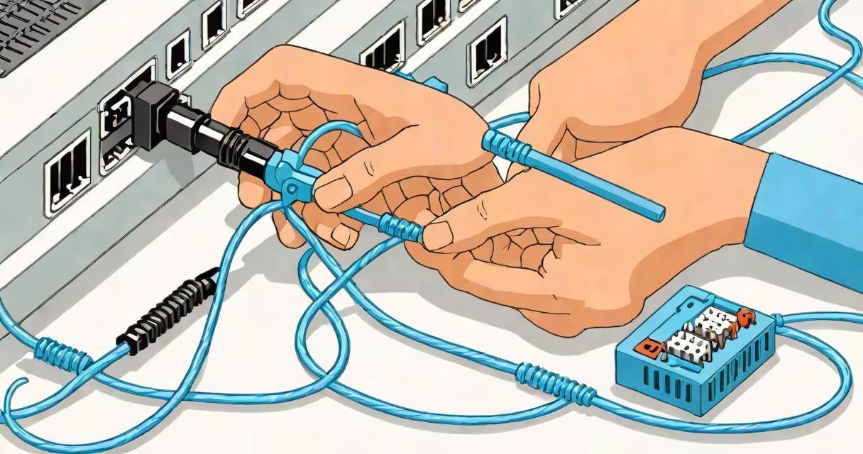
Wiring a cat 5 plug involves inserting the individual wires of a twisted-pair Ethernet cable into the correct positions inside an RJ45 connector and securing them with a crimping tool. This process creates a physical interface for connecting computers, routers, and switches via a wired network.
The standard for wiring a Cat 5 plug follows either the T568A or T568B pinout configuration. Both ensure consistent signal transmission and compatibility across devices. The T568B pattern is more common in North American installations due to its alignment with older telephone wiring standards.
Each wire in a Cat 5 cable is color-coded and twisted in pairs to reduce electromagnetic interference. When terminating the cable, the twist must be preserved as close to the connector as possible-typically no more than 13 mm (½ inch)-to maintain signal integrity. Failure to do so increases crosstalk and reduces bandwidth performance.
When a device sends data over Ethernet, electrical signals travel through specific pairs of wires within the Cat 5 cable. The RJ45 plug's eight pins correspond to these pairs. Pin 1 and 2 carry the transmit signal, while pins 3 and 6 handle receive. Pins 4 and 5, along with 7 and 8, are unused in 10/100 Mbps Ethernet but may be used in Gigabit Ethernet (1000BASE-T).
Proper wiring helps each wire connects to the correct pin on both ends of the cable. Mismatched wiring causes communication failures, intermittent connectivity, or reduced speeds. A correctly wired patch cable allows full-duplex communication between devices at maximum supported speeds.
After inserting the wires into the connector, the crimping tool compresses metal contacts inside the plug. These contacts pierce the insulation of each wire and make direct contact with the conductor. The tool also secures the strain relief boot around the cable jacket to prevent pull-out damage.
A Cat 5 plug consists of a plastic housing, eight gold-plated metal contacts, a strain relief boot, and internal locking tabs. The housing is molded to fit the RJ45 standard size and includes a small notch that aligns with the cable's outer sheath during crimping.
There are two primary wiring standards:
| Pin | T568A Color | T568B Color |
|---|---|---|
| 1 | Green/White | Orange/White |
| 2 | Green | Orange |
| 3 | Orange/White | Green/White |
| 4 | Blue | Blue |
| 5 | Blue/White | Blue/White |
| 6 | Orange | Green |
| 7 | White/Brown | White/Brown |
| 8 | Brown | Brown |
Use T568B for most new installations. Mixing standards on both ends results in a crossover cable, which is only useful for connecting similar devices (e.g., two PCs directly). For connecting dissimilar devices-like a PC to a switch-use the same standard on both ends (straight-through cable).
Some plugs feature shielded contacts or reinforced strain relief for industrial environments. Low-voltage applications such as PoE (Power over Ethernet) require cables rated for higher current and proper grounding. Always verify the cable's category rating (Cat 5e, Cat 6) before termination.
Wiring a cat 5 plug enables reliable, high-speed networking in homes, offices, and data centers. It supports 100 Mbps speeds at 100 MHz bandwidth and up to 1 Gbps at 250 MHz when using Cat 5e or higher-rated cables.
Common applications include connecting desktops to wall jacks, linking switches and routers, setting up IP cameras, and installing smart home hubs. In commercial settings, structured cabling systems rely on consistent termination practices to pass certification tests like those from the Telecommunications Industry Association (TIA).
For example, a small business installing a new office network might run 20 Cat 5e cables from a central patch panel to workstations. Each cable requires properly wired Cat 5 plugs at both ends. Using a consistent method-such as T568B-helps all connections function without troubleshooting delays.
Many assume that any order of wires works as long as they're inserted. This leads to failed connections or unstable performance. A single reversed pair can cause link failure even if the cable appears intact.
Another error is leaving too much untwisted wire beyond the connector. The standard limits this to 13 mm. Exceeding it introduces noise and signal degradation, especially at higher frequencies. Testing tools like a Fluke LinkRunner show errors such as "near-end crosstalk" or "attenuation" when this occurs.
Some users believe that crimping too hard improves connection quality. Over-crimping damages the contacts and can break the wire inside. The correct pressure is achieved when the tool's lever fully closes and the contacts snap into place. A properly crimped plug shows no visible gaps between the boot and the housing.
One non-obvious fact: the color coding of Cat 5 cables varies slightly between manufacturers. While ANSI/TIA-568-B specifies the standard colors, some brands use alternate shades. Always refer to the actual wire, not the label, when matching colors to pins.
I once installed a Cat 5e network for a client who had experienced frequent disconnections. After testing, I found that several cables had incorrect wiring-specifically, swapped pairs in the T568B sequence. Re-terminating the cables with the correct pinout resolved the issue. The client reported stable internet access and faster file transfers afterward.
For a practical example: To wire a Cat 5 plug using T568B:
Always test every cable before deployment. A single miswired pair can disrupt entire network segments.