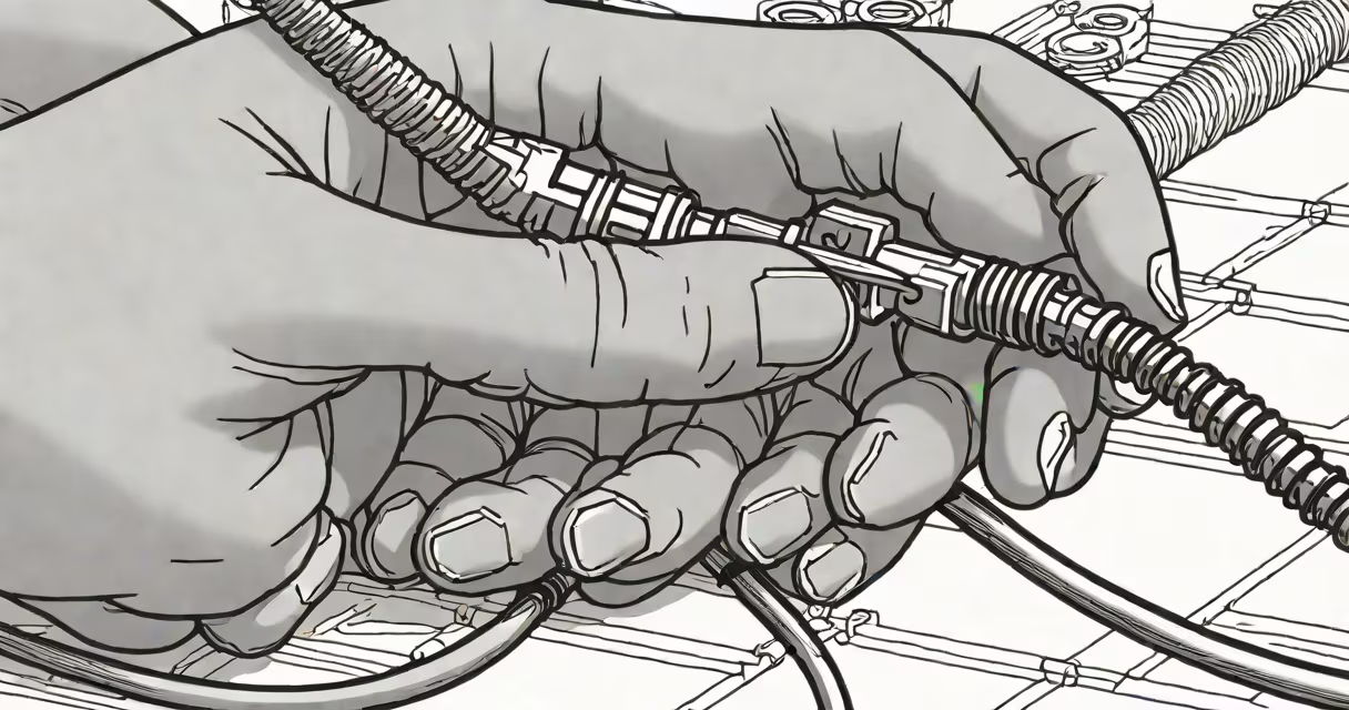
wiring a cat5e plug involves terminating an Ethernet cable with an RJ45 connector using a specific wire sequence to ensure reliable gigabit-speed network connections. The process requires stripping the outer jacket, arranging the eight internal wires in a precise order, trimming them flush, and inserting them into the connector's pins before crimping.
The standard wiring method for Cat5e cables is T568B, defined by the Telecommunications Industry Association (TIA). This configuration assigns colors to specific pin positions: white/orange, orange, white/green, blue, white/blue, green, white/brown, brown. Using this layout ensures compatibility across switches, routers, and network interface cards.
Incorrect wiring causes signal degradation, intermittent connectivity, or complete failure. A single misaligned wire can reduce bandwidth from 1 Gbps to 100 Mbps or lower. Proper termination maintains signal integrity through consistent impedance and minimized crosstalk between pairs.
Each of the eight conductors inside a Cat5e cable forms a twisted pair. Two pairs are used for data transmission: one pair sends signals, the other receives. The remaining two pairs handle power delivery in PoE (Power over Ethernet) setups. When properly wired, these pairs remain isolated to prevent interference.
During crimping, metal contacts inside the RJ45 connector pierce the insulation and make direct contact with the conductor. If wires aren't aligned correctly or cut unevenly, the connection may fail or degrade under load. A poorly terminated plug can cause packet loss, slow speeds, or disconnections during peak usage.
Testing with a cable certifier confirms performance. A basic continuity tester checks for shorts and opens, while a professional analyzer measures insertion loss, near-end crosstalk (NEXT), and return loss. These metrics determine whether the link meets Category 5e specifications.
You need a Cat5e cable, an RJ45 connector, a wire stripper, a crimping tool, and optionally a cable tester. The stripper removes the outer sheath without nicking the inner wires. The crimping tool compresses the connector's pins onto the conductors and secures the strain relief.
Use a flat surface and good lighting. Work slowly-rushing leads to errors. Always verify the wire order before crimping. A common mistake is reversing the order between T568A and T568B, which breaks compatibility with some network equipment.
For consistency, follow the T568B standard unless your network specifically uses T568A. Mixing standards on both ends creates a crossover cable, which only works between certain devices. Most modern switches auto-detect and correct for this, but relying on auto-MDI-X increases risk in mission-critical environments.
| Pin | Color (T568B) | Function |
|---|---|---|
| 1 | White/Orange | Data Transmit + |
| 2 | Orange | Data Transmit − |
| 3 | White/Green | Data Receive + |
| 4 | Blue | Not used (pair 2) |
| 5 | White/Blue | Not used (pair 2) |
| 6 | Green | Data Receive − |
| 7 | White/Brown | Not used (pair 3) |
| 8 | Brown | Not used (pair 3) |
One frequent error is leaving too much exposed wire. The conductors should extend no more than 1/4 inch beyond the connector's entry point. Excess length introduces capacitance and signal reflection, degrading performance.
Another issue is not aligning the wires in the correct order. Even swapping two adjacent wires can cause data corruption. Always double-check against the T568B chart before crimping.
When the crimp fails, the connector won't hold. Re-strip and re-terminate. Do not reuse a damaged connector. The plastic housing can crack during removal, compromising strain relief and long-term durability.
I once terminated a Cat5e cable for a home office router. The original cable had frayed insulation and inconsistent wire alignment. After stripping, I arranged the wires in T568B order and trimmed them precisely. Using a crimping tool, I secured the connector. A subsequent test with a Fluke Networks LinkRunner showed full 1 Gbps throughput and zero errors.
This result matched the manufacturer's specification for Category 5e cables. Without proper termination, even a new cable can fail under load. The test confirmed that correct wiring prevents signal loss and supports stable high-speed communication.
wiring a cat5e plug is not interchangeable with older standards like Cat3 or Cat5. Cat5e supports higher frequencies (up to 100 MHz) and reduced crosstalk compared to earlier versions. Using Cat5e components with Cat3-rated tools or connectors can lead to performance issues.
It is also not a one-size-fits-all task. Some installations require shielded Cat5e (STP) cables and grounded connectors. Unshielded (UTP) cables are sufficient for most residential and small business applications, but industrial settings demand shielding to resist electromagnetic interference.
A key distinction: never assume a cable works after crimping. Always test with a certified cable tester. A visual inspection may show correct wire order, but internal faults like shorted pairs or poor contact can go undetected.
Always label both ends of the cable. Use color-coded tags or printed labels to identify purpose (e.g., "Office Printer" or "Server Room"). This simplifies troubleshooting and reduces downtime during maintenance.
Keep spare connectors and tools on hand. A single failed termination can delay a project. Store unused cables coiled loosely-not tightly wound-to avoid kinks that affect signal integrity.
Follow the 100-meter maximum distance rule. Cat5e cables must not exceed 100 meters between endpoints. Beyond that, signal attenuation exceeds acceptable limits, leading to dropped packets and reduced throughput.
For longer runs, use fiber optic cabling or install a switch to extend reach. Termination points should be within 90 meters of the endpoint, allowing 10 meters for patch cords.
When in doubt, consult the TIA/EIA-568-B.2 standard, which defines the electrical and mechanical requirements for structured cabling systems. The document is freely available from the TIA website and includes detailed diagrams and testing procedures.
After completing the termination, verify the connection with a network tester. A blinking LED on the port indicates link status. If no light appears, check the physical connection, cable path, and device configuration.
Understanding how to wire a cat5e plug ensures reliable, high-performance networking. It's a foundational skill for IT professionals, network administrators, and anyone building a custom wired infrastructure.