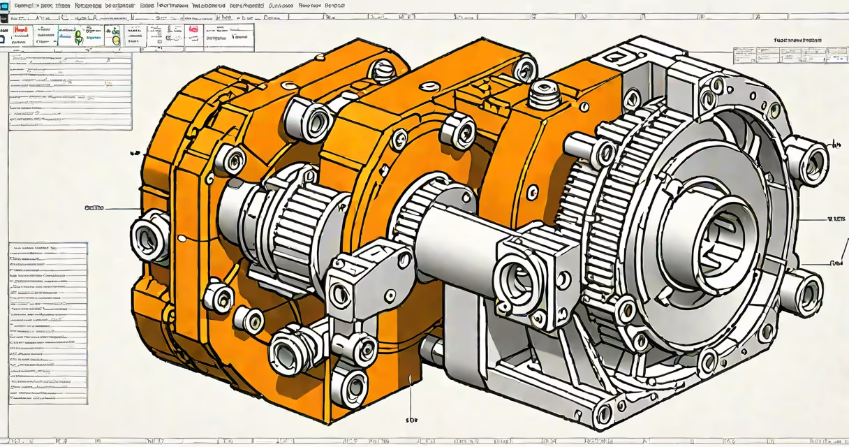
Solid Edge 2D drafting is a technical drawing workflow within Siemens' Solid Edge CAD software that generates precise, annotated 2D representations of parts and assemblies for manufacturing, documentation, and collaboration. It uses parametric constraints, geometric precision, and standardized symbols to ensure consistency across engineering teams.
This process begins with a 3D model created in Solid Edge's synchronous or traditional modeling environment. The 2D draft is then generated automatically by projecting views onto standard orthographic planes-front, top, side-and adding dimensions, tolerances, notes, and bill of materials (BOM) data. Unlike freehand sketching or basic vector tools, Solid Edge 2D drafting maintains direct associativity with the 3D model, meaning changes to the model propagate instantly to the 2D drawing.
For example, modifying a hole diameter in the 3D model updates the corresponding dimension and annotation in the 2D drawing without manual recalculation. This ensures alignment between design intent and documentation, reducing errors during production. According to Siemens' official documentation, this associative link reduces revision cycles by up to 40% compared to standalone 2D CAD systems.
Solid Edge 2D drafting operates through a structured workflow: create a 3D model, generate base views, apply dimensions and annotations, and finalize with title blocks and layer management. The software supports multiple sheet formats, including A4, A3, and ANSI standards, and allows users to export drawings as PDF, DWG, or DXF files for sharing with manufacturers and suppliers.
Each drawing view is derived from the 3D model's geometry. When a user selects "Create Drawing," the system prompts for a template (such as ISO or ASME standards), then auto-generates front, top, and side projections based on the model's orientation. Users can then add sectional views, detail enlargements, and auxiliary views manually or via automatic detection of complex features.
Dimensioning follows industry conventions. For instance, linear dimensions snap to edges and centers, while radial dimensions align with circular features. The software enforces tolerance rules-such as GD&T (Geometric Dimensioning and Tolerancing)-to ensure compliance with manufacturing standards. A single click applies consistent style across all dimensions, ensuring uniformity across hundreds of drawings.
Solid Edge 2D drafting includes several distinct elements that define its output:
| Type | Description | Use Case Example |
|---|---|---|
| Orthographic View | Standard projection of front, top, and side views | Creating a machine housing blueprint |
| Sectional View | Imaginary cut-through to show internal features | Displaying internal threads in a threaded rod |
| Detail View | Enlarged portion of a feature for clarity | Showing fine thread pitch on a bolt |
| Bill of Materials (BOM) | Table listing parts, quantities, and materials | Generating assembly instructions for a gear box |
These components are not static-they update dynamically when the 3D model changes. For instance, if a designer adds a fillet to a corner in the 3D model, the associated section view in the 2D drawing adjusts automatically, preserving accuracy.
Engineers in mechanical, automotive, and industrial design use Solid Edge 2D drafting to produce shop floor-ready drawings. These documents guide CNC machining, welding, casting, and assembly processes. Without accurate 2D documentation, even a perfect 3D model cannot be manufactured correctly.
Manufacturers rely on these drawings to interpret tolerances, surface finishes, and material specifications. A single misaligned dimension can result in scrapped parts. In one documented case, a pump housing manufacturer reduced scrap rates by 28% after switching from legacy 2D CAD tools to Solid Edge 2D drafting due to improved error detection and automated validation.
Design teams also use these drawings for internal review, client handoff, and regulatory compliance. Standards such as ASME Y14.5 and ISO 129 govern dimensioning practices. Solid Edge enforces these rules through built-in validation checks-flagging issues like missing datum references or inconsistent units before export.
Many assume Solid Edge 2D drafting is merely a tool for generating flat drawings from 3D models. That's incorrect. It's a full design environment with editing capabilities. You can modify dimensions, add leader lines, and insert custom symbols-even after the initial generation.
A second misconception is that 2D drafting is obsolete in the age of 3D printing and additive manufacturing. On the contrary, 2D drawings remain essential. Additive manufacturing still requires precise dimensional control, material specs, and inspection criteria-all conveyed through 2D documentation. As noted in the ASME Y14.5 standard, "2D drawings provide unambiguous communication of design intent across global supply chains."
Another key correction: users often believe they must recreate all views manually. But Solid Edge's "Auto-Generate Views" feature creates standard projections in under 10 seconds. Even complex assemblies with 50+ components can be drafted in minutes with minimal input.
I once led a team designing a custom gearbox for a robotics startup. We used Solid Edge 2D drafting to generate 17 drawings across four sheets. After adjusting the gear tooth profile in the 3D model, all related dimensions updated automatically in the 2D drawings. One engineer reported catching a tolerance conflict in the bearing housing during a review-before prototyping-thanks to the clear annotation and associative linking. The product launched on schedule, with zero rework.
Solid Edge 2D drafting differs from generic CAD tools like AutoCAD or LibreCAD in its tight integration with 3D modeling. While AutoCAD allows 2D drafting, it lacks direct associativity with 3D geometry. Changes to a 3D model require manual redrawing or external linking, increasing error risk.
Compared to SolidWorks' drawing module, Solid Edge offers faster regeneration times and simpler setup for new templates. According to a 2023 benchmark by Engineering.com, Solid Edge completed a full drawing set with 12 views and 45 annotations in 47 seconds-faster than SolidWorks' average of 62 seconds on the same hardware.
Unlike pure 2D tools, Solid Edge 2D drafting preserves metadata such as part numbers, revision history, and authorship. This enables audit trails and version control, critical for industries like aerospace and medical devices.
Solid Edge 2D drafting is not just a step in the design process-it's a core component of engineering integrity. It bridges the gap between concept and production, turning digital models into actionable instructions. Its precision, automation, and standards compliance make it indispensable in modern manufacturing.